Introduction
This is a user manual for the GLASSS web application, a tool created by Maffeis Engineering SpA for the analysis and design of glass structures. This document provides a comprehensive guide to using the app, from defining the geometry and built-up of your glass panel to applying loads, running an analysis, and generating a report.
What is GLASSS?
GLASSS is an advanced web application designed to simplify the complex process of designing and analyzing glass structures. By using this tool, engineers and designers can accurately define the properties of a glass panel, apply various load conditions, and perform a detailed Finite Element Method (FEM) analysis. This ensures that the glass structure meets safety standards and performs as expected under different environmental and mechanical stresses.
Alongside the FEM analysis, a novel Generative AI is presented for creating a fast preview.
Main tabs
The GLASSS interface is structured around a workflow composed of nine main sections:
- Geometry: How to define the shape and dimensions of your glass panel.
- Supports: How to add and configure edge and point supports.
- Loads: How to define and apply various load types.
- Options: How to set analysis parameters and safety standards.
- Analysis: How to run the analysis and view results.
- Check: How to interpret the working ratios and stress checks.
- Report: How to generate a final report of your project.
By following the sections in order, you can complete a full analysis of your glass structure from start to finish.

To enable mesh visualization, click Show Mesh. Clicking the Data panel will open a dropdown menu with various options. Remember to click Save frequently, as auto-save is not available.
Geometry
This section allows you to define the geometric properties of your glass panel.
View
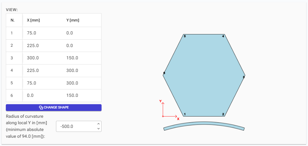
Define the shape of your geometry by entering the polygon points one by one in a counterclockwise direction. To change the number of points, click the "Change Shape" button. You can also define the radius of curvature for a cylindrical shape. The global axes are displayed for reference.
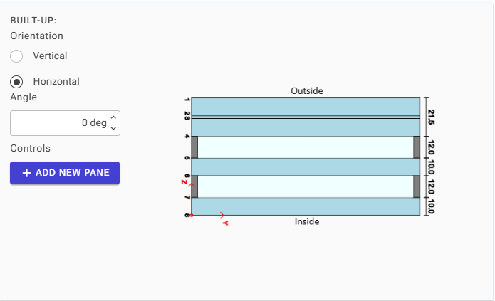
Built-up
This section shows the layers that make up your glass package. The surfaces are numbered from outside to inside, and the thickness of each package is displayed on the right side of the image.
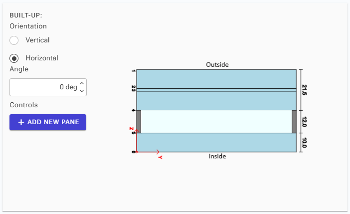
Orientation
Select a vertical or horizontal orientation or set a custom rotation angle in degrees. The rotation is performed around the Y-axis, following the right-hand rule, with respect to the orientation chosen.
Adding Layers
To add a new package and create a gas camera, click on "Add New Pane". A new pane will always be placed on the inside of the existing glass package.
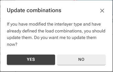
If your glass package includes interlayers, it's crucial to update the parameters of your load combinations to reflect the secant modulus of these interlayers. This ensures accurate calculations for their behavior under load.
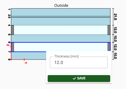
Adjusting Thickness
- To adjust the camera's thickness, click on the camera icon and update its thickness in millimeters.
- To modify a glass pane's thickness, click on the glass pane itself to update both the nominal and calculated thickness.
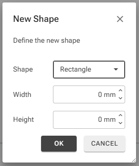
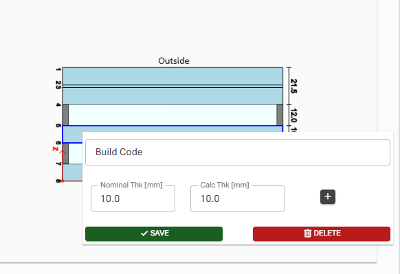
Adding New Layers
You can add a new layer in two ways:
- Click the "+" button.
- Enter the build-up code.
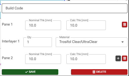
- Set the nominal and calculated thickness for each glass layer. Then, select the number of interlayers so that their total thickness equals 0.36 times the chosen quantity. Choose the interlayer's material type from the dropdown menu.
Interlayer Specifications
You can adjust the interlayer specifications by:
- Setting the Quantity (Qty) of Minimum Base Thickness: The total interlayer thickness will be calculated as 0.38×Qty.
- Choosing the Material: Select from a list of commonly used materials.
Note: If your desired material is not available in the list, you can manually input its secant modulus directly into the load cases table, found within the "Loads" section.
Supports
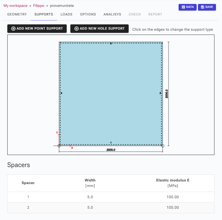
Adjust edge supports, or add point supports and hole fixings in this section. To modify an edge support, click on the desired edge.
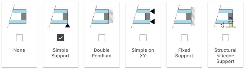
You have several support types to choose from:
- None: No support is applied.
- Simple Support: Fixed out of plane direction in bottom surfaces of each package.
- Double Pendulum: Fixed the in plane directions in all surfaces.
- Simple on XY: Fixed in plane directions in bottom surfaces of each package.
- Fixed Support: Fixed all directions in all surfaces.
- Structural Silicone Support: A silicone material is modelled to support the inside surface.
Structural Silicone Parameters
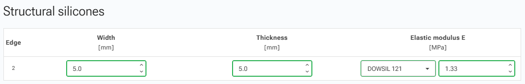
If "Structural Silicone Support" is selected, a figure will appear, allowing you to define the following parameters for the silicone seal:
- Width
- Thickness
- Elastic Modulus: select from listed materials or put a custom value.
The silicone is modelled as point springs at each node of the edge's mesh, with stiffness values calculated based on the data you provide.
Spacer Specifications
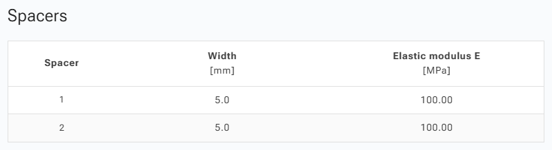
If cameras are present in your design, a figure will appear, allowing you to select the spacer specifications for each camera. This includes the width and elastic modulus for each.
In cases with two cameras, one refers to the outside camera and the second to the inside camera.
The spacer is modelled using truss elements that connect the mesh nodes at the edge across the camera.
Loads
Define your loads and load combinations here. All loads have a specified duration, which is used to calculate the secant modulus of interlayers for load combinations.
Load Types
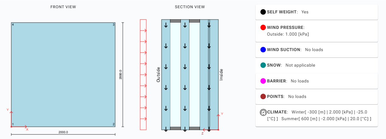
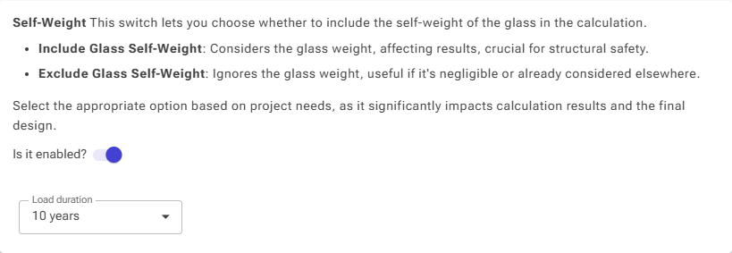
Self-Weight
Enable this to apply gravity along the negative global Z-axis.
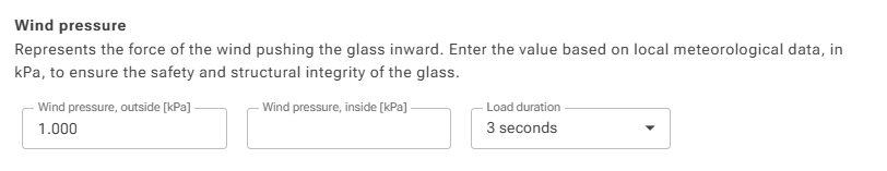
Wind Load
A uniform load applied normal to the glass surface. Specify the intensity in kPa for pressure and suction on both inside and outside surfaces.
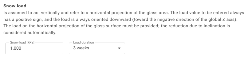
Snow Load
A uniform load in kPa, projected onto the horizontal footprint. It's always applied to the top side with respect to the Z-axis.
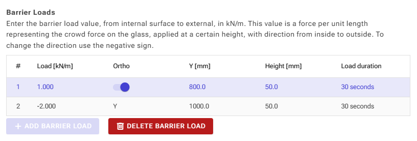
Barrier Load
A horizontal force defined by:
- Intensity: kN/m. A positive value is from the inside surface; a negative value is from the outside.
- Height: The height along the global Z-axis where the load is applied.
- Load Width: The spacing in mm for the load's width.
- Orientation: Choose to apply the load orthogonal to the surface or horizontally.
Options
You can set the maximum allowable deflection and define the verification standard:
- ASTM 1300 (USA)
- EN 16612 (European Union)
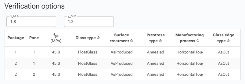
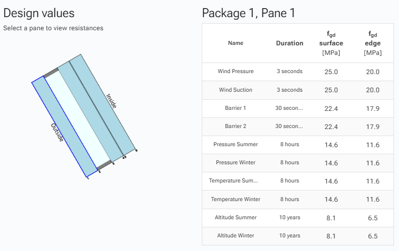
If you choose the EN 16612 standard, you can set the gamma coefficients (γM) for material safety factors. These coefficients are used to calculate the design resistance (fgd) based on the characteristic glass resistance (fgk). You can view the values for load duration, fgd at the surface, and fgd at the edge.
Analysis
You have two options for analysis:
- Run Analysis: This performs a full Finite Element Method (FEM) analysis.
- Run Inference: This provides a quick preview of results using AI-driven calculations.
"Check and Report" options are only available after a successful FEM analysis.
Run Analysis
The analysis is performed in the cloud and returns displacements and stresses for every load combination.
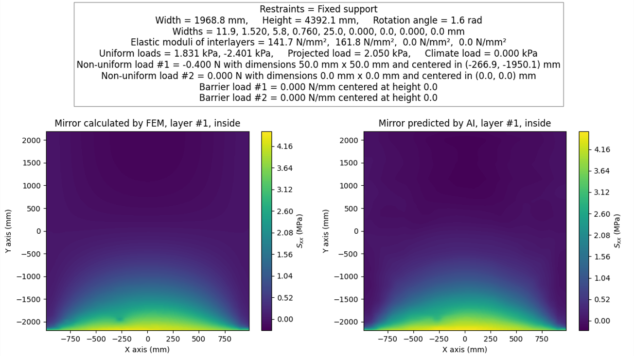
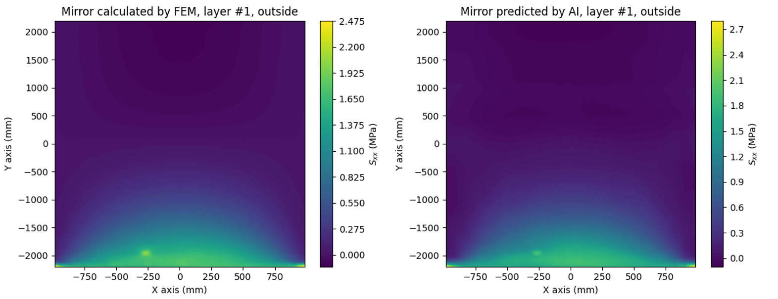
Run Inference
GLASSS AI is based on a neural network trained and validated on a very large dataset of glasses. It exploits state-of-the-art deep learning techniques to predict the outcome of typical FEM calculations over stresses and displacements. This tool's sole purpose is to provide an ultra-fast estimation of the order of magnitude of stresses and deformations.
The AI system does not allow the user to obtain a certified document. The use of FEM is mandatory to obtain a certification of the calculation.
Available Cases
- Rectangular base of the glass structure.
- Self-weight included.
- Edge constraints: simple support on all edges, simple support on 2 opposite edges, or fixed support on one edge.
- Horizontal or vertical glass.
- No holes within the glass structure.
- Dimensions between 50 cm × 50 cm and 3.2 m × 6 m.
- Maximum five layers of glass with PVB and/or air interlayers.
- Total uniform load on each surface within [−5 kPa, +5 kPa].
Comparison between FEM and AI outputs
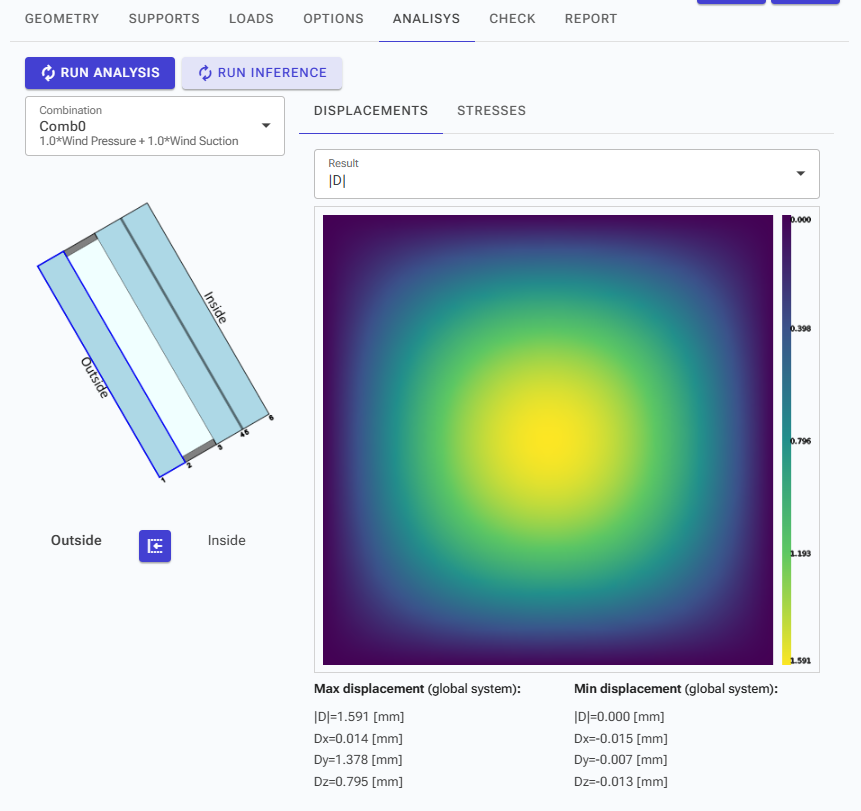
Viewing Results
If the analysis is successful, you can view displacements and stresses.
- Select the Load Combination: Choose the desired load combination from the combination menu.
- Select the Layer: Use your mouse pointer to click on the icon for the specific layer you wish to view.
- Choose Surface: Select whether you want to see the outside or inside surface.
Understanding Displacement and Stress Results
For displacement results, you can view:
- The absolute value of deformation.
- The components of deformation along the global axes.
For stress results, you can see:
- Maximum principal stresses (σ1, σ2, σ3): The first principal stress represents maximum traction, and the third represents maximum compression.
- Sigma X (σx): Stress along the global X-axis.
- Sigma Y (σy): Stress along the global Y-axis.
- Tau XY (τxy): Shear stress along the global XY plane.
- Sigma ID (σid): Von Mises stress.
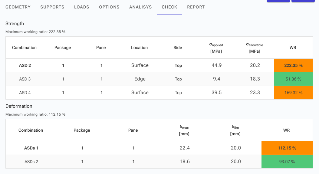
Check
This section displays the working ratios for each load case. Results are color-coded to easily identify whether they pass or fail.
For each load condition, you can view the maximum calculated values alongside the allowable limits, specifying the package, pane, and location of the stress.
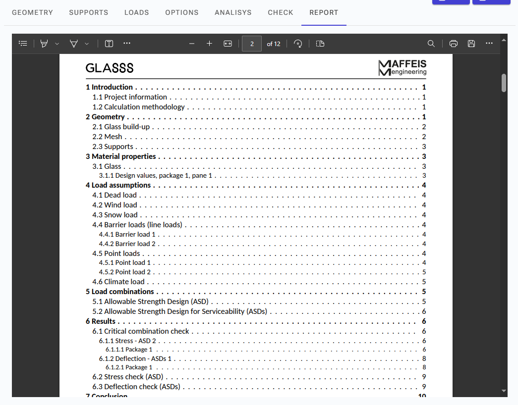
Report
You can generate a detailed report of your calculations. This report includes all relevant data and analysis details.
To save or print the report, use the download or print buttons located in the top bar.
Please ensure you adhere to the terms of use as accepted upon accessing the service.